Product Description
Conveyor Pulley is manufactured as per customer requirement,with main design under national standard,quality inspection focusing on shaft core,welded joint,rubber material and hardness,dynamic balance and so on for longer product life time.
| Drive/Head Pulley – A conveyor pulley used for the purpose of driving a conveyor belt. Typically mounted in external bearings and driven by an external drive source. |
| Return/Tail Pulley – A conveyor pulley used for the purpose of redirecting a conveyor belt back to the drive pulley. Tail pulleys can utilize internal bearings or can be mounted in external bearings and are typically located at the end of the conveyor bed. Tail pulleys commonly serve the purpose of a Take-Up pulley on conveyors of shorter lengths. |
| Snub Pulley – A conveyor pulley used to increase belt wrap around a drive pulley, typically for the purpose of improving traction. |
| Take-Up Pulley – A conveyor pulley used to remove slack and provide tension to a conveyor belt. Take-Up pulleys are more common to conveyors of longer lengths. |
| Bend Pulley – A conveyor pulley used to redirect the belt and provide belt tension where bends occur in the conveyor system. |
The specification of pulley:
Drive Drum: is the main component of power transmission. The drum can be divided into single drum (the angle of the belt to the drum is 210 ° ~ 230 °) , Double Drum (the angle of the belt to the drum is up to 350 °) and
multi-drum (used for high power) .
Bend Drum: is used for changing the running direction of the conveyor belt or increasing the surrounding angle of the conveyor belt on the driving roller, and the roller adopts a smooth rubber surface . The drum shaft shall be forgings and shall be nondestructive tested and the inspection report shall be provided.
The Various Surface of Pulley:
Conveyor pulley lagging is essential to improve conveyor belt performance, the combination of our pulley lagging can reduces belt slippage, improve tracking and extends life of belt, bearing & other components.
| PLAIN LAGGING:This style of finish is suitable for any pulley in the conveyor system where watershed is not necessary. It provides additional protection against belt wear, therefore, increasing the life of the pulley. |
| DIAMOND GROOVE LAGGING:This is the standard pattern on all Specdrum lagged conveyor pulleys. It is primarily used for reversing conveyor drive pulleys. It is also often used to allow bi-directional pulley rotation, and the pattern allows water to be dispersed away from the belt. |
| HERRINGBONE LAGGING:The herringbone pattern’s grooves are in the direction of rotation, and offers superior tractive properties. Each groove allows water and other liquids to escape between the face of the drum pulley and the belt. Herringbone grooved pulleys are directional and should be applied to the conveyor in a manner in which the grooves point toward the direction of the belt travel. |
| CHEVRON LAGGING:Some customers specify that the points of the groove should meet – as done in Chevron styled lagging. As before with the herringbone style, this would be used on drive drum pulleys and should be fitted in the correct manner, so as to allow proper use of the pattern and water dispersion also. |
| CERAMIC LAGGING:The Ceramic tiles are moulded into the lagging which is then cold bonded to the drum pulley. This style of finish allows excellent traction and reduces slippage, meaning that the belt tension is lower and, therefore as a result, increases the life of the pulley. |
| WELD-ON STRIP LAGGING: Weld-On Strip Lagging can be applied to bi-directional pulleys, and also has a finish to allow the easy dispersion of water or any fluids between the drum pulley and the belt. |
The Components of Pulley:
| 1. Drum or Shell:The drum is the portion of the pulley in direct contact with the belt. The shell is fabricated from either a rolled sheet of steel or from hollow steel tubing. |
| 2.Diaphragm Plates: The diaphragm or end plates of a pulley are circular discs which are fabricated from thick steel plate and which are welded into the shell at each end, to strengthen the drum.The end plates are bored in their centre to accommodate the pulley Shaft and the hubs for the pulley locking elements. |
| 3.Shaft :The shaft is designed to accommodate all the applied forces from the belt and / or the drive unit, with minimum deflection. The shaft is located and locked to the hubs of the end discs by means of a locking elements. The shaft and hence pulley shafts are often stepped. |
| 4.Locking Elements:These are high-precision manufactured items which are fitted over the shaft and into the pulley hubs. The locking elements attach the pulley firmly to the shaft via the end plates. |
| 5.Hubs:The hubs are fabricated and machined housings which are welded into the end plates. |
| 6.Lagging: It is sometimes necessary or desirable to improve the friction between the conveyor belt and the pulley in order to improve the torque that can be transmitted through a drive pulley. Improved traction over a pulley also assists with the training of the belt. In such cases pulley drum surfaces are `lagged` or covered in a rubberized material. |
| 7.Bearing: Bearings used for conveyor pulleys are generally spherical roller bearings, chosen for their radial and axial load supporting characteristics. The bearings are self-aligning relative to their raceways, which means that the bearings can be ‘misaligned’ relative to the shaft and plummer blocks, to a certain degree. In practical terms this implies that the bending of the shaft under loaded conditions as well as minor misalignment of the pulley support structure, can be accommodated by the bearing. |
The Production Process of Pulley:
Our Products:
| 1.Different types of Laggings can meet all kinds of complex engineering requirements. |
| 2.Advanced welding technology ensures the connection strength between Shell and End-Disk. |
| 3.High-strength Locking Elements can satisfy torque and bending requirements. |
| 4.T-shape End-Discs provide highest performance and reliability. |
| 5.The standardized Bearing Assembly makes it more convenient for the end user to replace it. |
| 6.Excellent raw material and advanced processing technology enable the shaft can withstand enough torque. |
| 7.Low maintenance for continued operation and low total cost of ownership. |
| 8.Scientific design process incorporating Finite Element Analysis. |
Our Workshop:
|
Shipping Cost:
Estimated freight per unit. |
To be negotiated |
|---|
| Material: | Carbon Steel |
|---|---|
| Surface Treatment: | Baking Paint |
| Motor Type: | Frequency Control Motor |
| Samples: |
US$ 40/Piece
1 Piece(Min.Order) | Order Sample Free sample
|
|---|
| Customization: |
Available
| Customized Request |
|---|
How to use the pulley system
Using a pulley system is a great way to move things around your home, but how do you use a pulley system? Let’s look at the basic equations that describe a pulley system, the types of pulleys, and some safety considerations when using pulleys. Here are some examples. Don’t worry, you’ll find all the information you need in one place!
Basic equations of pulley systems
The pulley system consists of pulleys and chords. When the weight of the load is pulled through the rope, it slides through the groove and ends up on the other side. When the weight moves, the applied force must travel nx distance. The distance is in meters. If there are four pulleys, the distance the rope will travel will be 2×24. If there are n pulleys, the distance traveled by the weight will be 2n – 1.
The mechanical advantage of the pulley system increases with distance. The greater the distance over which the force is applied, the greater the leverage of the system. For example, if a set of pulleys is used to lift the load, one should be attached to the load and the other to the stand. The load itself does not move. Therefore, the distance between the blocks must be shortened, and the length of the line circulating between the pulleys must be shortened.
Another way to think about the acceleration of a pulley system is to think of ropes and ropes as massless and frictionless. Assuming the rope and pulley are massless, they should have the same magnitude and direction of motion. However, in this case the quality of the string is a variable that is not overdone. Therefore, the tension vector on the block is labeled with the same variable name as the pulley.
The calculation of the pulley system is relatively simple. Five mechanical advantages of the pulley system can be found. This is because the number of ropes supporting the load is equal to the force exerted on the ropes. When the ropes all move in the same direction, they have two mechanical advantages. Alternatively, you can use a combination of movable and fixed pulleys to reduce the force.
When calculating forces in a pulley system, you can use Newton’s laws of motion. Newton’s second law deals with acceleration and force. The fourth law tells us that tension and gravity are in equilibrium. This is useful if you need to lift heavy objects. The laws of motion help with calculations and can help you better understand pulley systems.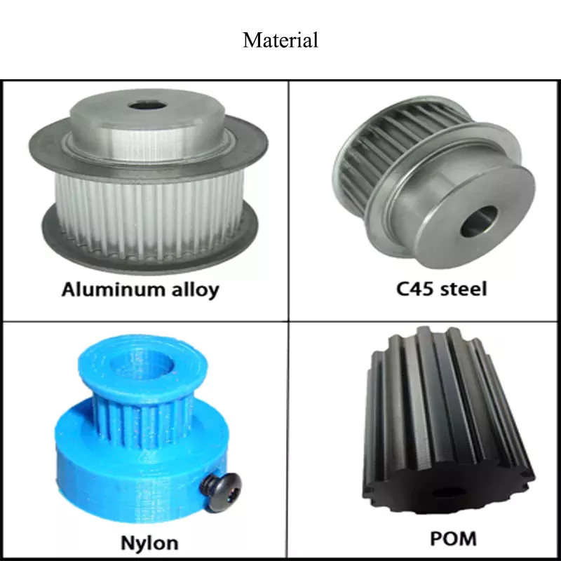
Types of pulleys
Different types of pulleys are commonly used for various purposes, including lifting. Some pulleys are flexible, which means they can move freely around a central axis and can change the direction of force. Some are fixed, such as hinges, and are usually used for heavier loads. Others are movable, such as coiled ropes. Whatever the purpose, pulleys are very useful in raising and lowering objects.
Pulleys are common in many different applications, from elevators and cargo lift systems to lights and curtains. They are also used in sewing machine motors and sliding doors. Garage and patio doors are often equipped with pulleys. Rock climbers use a pulley system to climb rocks safely. These pulley systems have different types of pinions that allow them to balance weight and force direction.
The most common type of pulley is the pulley pulley system. The pulley system utilizes mechanical advantages to lift weight. Archimedes is thought to have discovered the pulley around 250 BC. in ancient Sicily. Mesopotamians also used pulleys, they used ropes to lift water and windmills. Pulley systems can even be found at Stonehenge.
Another type of pulley is called a compound pulley. It consists of a set of parallel pulleys that increase the force required to move large objects. This type is most commonly used in rock climbing and sailing, while composite pulleys can also be found in theater curtains. If you’re wondering the difference between these two types of pulleys, here’s a quick overview:
Mechanical Advantages of Pulley Systems
Pulley systems offer significant mechanical advantages. The ability of the system to reduce the effort required to lift weights increases with the number of rope loops. This advantage is proportional to the number of loops in the system. If the rope had only one loop, then a single weight would require the same amount of force to pull. But by adding extra cycles, the force required will be reduced.
The pulley system has the advantage of changing the direction of the force. This makes it easier to move heavy objects. They come in both fixed and mobile. Pulleys are used in many engineering applications because they can be combined with other mechanisms. If you want to know what a pulley can do, read on! Here are some examples. Therefore, you will understand how they are used in engineering.
Single-acting pulleys do not change direction, but compound pulleys do. Their mechanical advantage is six. The compound pulley system consists of a movable pulley and a fixed pulley. The mechanical advantage of the pulley system increases as the number of movable wheels decreases. So if you have two wheels, you need twice as much force to lift the same weight because you need a movable pulley.
The mechanical advantage of a pulley system can be maximized by adding more pulleys or rope lengths. For example, if you have a single pulley system, the mechanical advantage is one of the smallest. By using two or three pulleys, up to five times the mechanical advantage can be achieved. You can also gain up to ten times the mechanical advantage by using multiple pulley systems.
The use of a single movable pulley system also adds to the mechanical advantage of the pulley system. In this case, you don’t have to change the direction of the force to lift the weight. In contrast, a movable pulley system requires you to move the rope farther to generate the same force. Using a compound pulley system allows you to lift heavy loads with ease.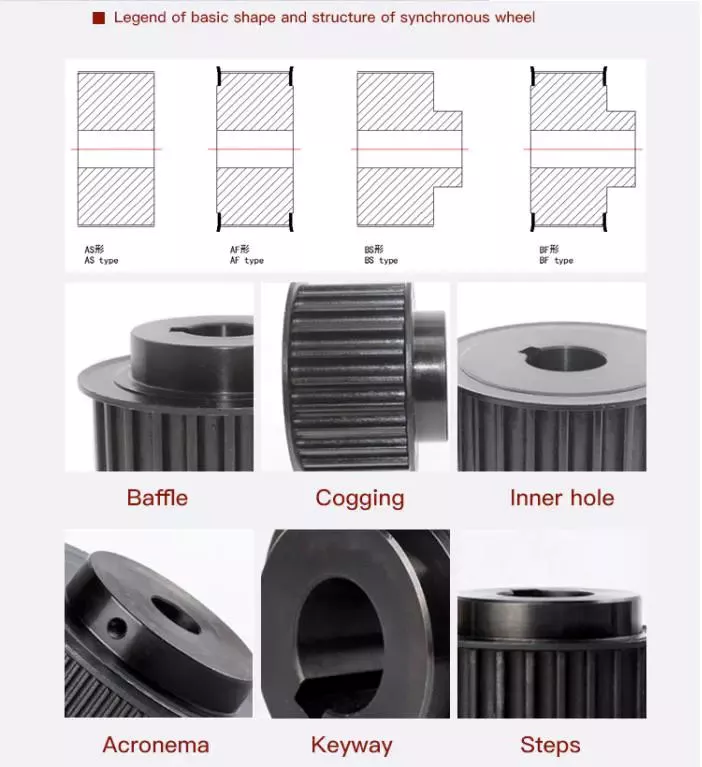
Safety Issues When Using Pulley Systems
Pulleys have an incredibly unique structure, consisting of a disc with a groove in the middle and a shaft running through it. A rope or cord is attached to one end of a pulley that turns when force is applied. The other end of the rope is attached to the load. This mechanical advantage means that it is much easier to pull an object using the pulley system than to lift the same object by hand.
Although pulley systems are a common part of many manufacturing processes, some employers do not train their workers to use them properly or install protection to prevent injury. It is important to wear proper PPE and follow standard laboratory safety practices during pulley system activities. Make sure any support structures are strong enough to handle the weight and weight of the rope or rope. If you do fall, be sure to contact your employer immediately.


editor by CX
2023-05-22